Basic flowchart diagram
The flowchart is one of the basic types of diagrams in Visio. Roughly speaking, that is used for creating the layout of process or development from beginning to end. Thanks to a Visio diagram it can easily add new shapes and merge and supplement labels. Learn step by step how to do it. If this guide has helped you, become a fan on Facebook and recommend this site to your friends, it can be useful for them too
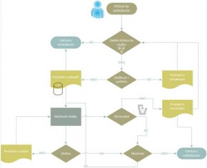
Setting a flowchart
We work with the Standard version of Visio 2010.
On the File> New select the type of diagram. Situated in the category Flowchart> Basic flowchart.
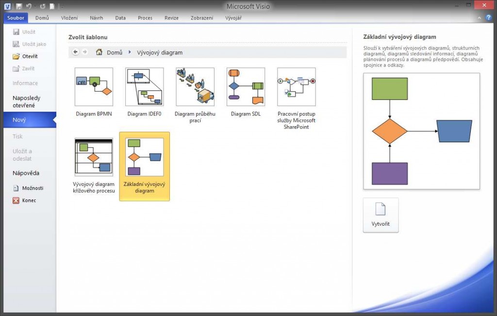
Confirm the choice to create and Visio moves us into a new drawing. On the left side activates the stencils of shapes – a library that we can put into diagrams.
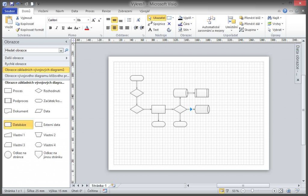
The list of shapes there can be found symbols representing the beginning of a process input and output objects, the decision node and many others. Adding to our drawing is yet a matter of dragging. Other shapes (to that already inserted) can be added via automatic connection. Just roll on the edge of the shapes in the drawing and arrow appears to basic shapes or place designated inserted shape from the stencil. The connector between the shapes is created automatically. If Auto-connect is not working, make sure you have it enabled. Turn on the View tab > Auto-connect.
Saving the drawing
The entire Drawing can be saved by selecting File > Save As.
Tip: drawing should end with .vsd for version 2010, for newer it is .vsdx.




Zanechat komentář